- 您现在的位置:买卖IC网 > Sheet目录473 > MAX2769BETI/V+T (Maxim Integrated)IC RCVR GPS UNIVERSAL 28TQFN
MAX2769B
Universal GPS Receiver
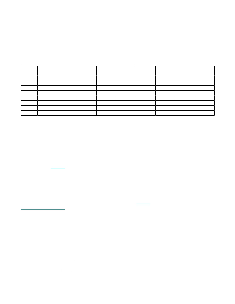
Table 2. Output Data Format
INTEGER
SIGN/MAGNITUDE
UNSIGNED BINARY
TWO’S COMPLEMENT BINARY
VALUE
7
5
3
1
-1
-3
-5
-7
1b
0
0
0
0
1
1
1
1
2b
01
01
00
00
10
10
11
11
3b
011
010
001
000
100
101
110
111
1b
1
1
1
1
0
0
0
0
2b
11
11
10
10
01
01
00
00
3b
111
110
101
110
011
010
001
000
1b
0
0
0
0
1
1
1
1
2b
01
01
00
00
11
11
10
10
3b
011
010
001
000
111
110
101
100
f TCXO 20MHz
Synthesizer
The MAX2769B integrates a 20-bit sigma-delta fractional-
N synthesizer allowing the device to tune to a required
VCO frequency with an accuracy of approximately
Q 30Hz. The synthesizer includes a 10-bit reference
divider with a divisor range programmable from 1 to
1023, a 15-bit integer portion main divider with a divisor
range programmable from 36 to 32767, and also a 20-bit
fractional portion main divider. The reference divider is
programmable by bits RDIV in the PLL integer division
ratio register (see Table 11 ), and can accommodate ref-
erence frequencies from 8MHz to 32MHz. The reference
divider needs to be set so the comparison frequency falls
between 0.05MHz to 32MHz.
The PLL loop filter is the only external block of the syn-
thesizer. A typical PLL filter is a classic C-R-C network
at the charge-pump output. The charge-pump output
sink and source current is 0.5mA by default, and the
LO tuning gain is 57MHz/V. As an example, see the
Typical Application Circuit for the recommended loop-
filter component values for f COMP = 1.023MHz and loop
bandwidth = 50kHz.
The desired integer and fractional divider ratios can be
calculated by dividing the LO frequency (f LO ) by f COMP .
f COMP can be calculated by dividing the TCXO frequency
(f TCXO ) by the reference division ratio (RDIV). For exam-
=
ple, let the TCXO frequency be 20MHz, RDIV be 1, and
the nominal LO frequency be 1575.42MHz. The following
method can be used when calculating divider ratios sup-
porting various reference and comparison frequencies:
Comparison Frequency = = 20MHz
RDIV 1
Integer Divider = 78(d) = 000 000 0100 1110 (binary)
Fractional Divider = 0.771 x 220 = 808452 (decimal) =
1100 0101 0110 0000 0100
In the fractional mode, the synthesizer should not be
operated with integer division ratios greater than 251.
Crystal Oscillator
The MAX2769B includes an on-chip crystal oscillator. A
parallel mode crystal is required when the crystal oscilla-
tor is being used. It is recommended that an AC-coupling
capacitor be used in series with the crystal and the XTAL
pin to optimize the desired load capacitance and to
center the crystal-oscillator frequency. Take the para-
sitic loss of interconnect traces on the PCB into account
when optimizing the load capacitance. For example, the
MAX2769B EV kit utilizes a 16.368MHz crystal that is
designed for a 12pF load capacitance. A series capaci-
tor of 23pF is used to center the crystal oscillator frequen-
cy, see Figure 1 . In addition, the 5-bit serial-interface
word, XTALCAP in the PLL Configuration register, can
be used to vary the crystal-oscillator frequency electroni-
cally. The range of the electronic adjustment depends on
how much the chosen crystal frequency can be pulled
by the varying capacitor. The frequency of the crystal
oscillator used on the MAX2769B EV kit has a range of
approximately 200Hz.
The MAX2769B provides a reference clock output. The
frequency of the clock can be adjusted to crystal-oscilla-
tor frequency, a quarter of the oscillator frequency, a half
of the oscillator frequency (f XTAL P 16MHz), or twice the
oscillator frequency, by programming bits REFDIV in the
PLL Configuration register.
f LO
= 78.771
Maxim Integrated
=
LO Frequency Divider =
f COMP
1575.42MHz
20MHz
14
发布紧急采购,3分钟左右您将得到回复。
相关PDF资料
MAX2769EVKIT+
KIT EVAL FOR MAX2769
MAX2821ETM+T
IC TXRX 802.11B 2.4GHZ 48-TQFN
MAX2829EVKIT
EVAL KIT MAX2828, MAX2829
MAX2830EVKIT+
KIT EVAL FOR MAX2830
MAX2831EVKIT+
KIT EVAL FOR MAX2831
MAX2837EVKIT+
KIT EVAL FOR MAX2837
MAX2838EVKIT+
KIT EVAL FOR MAX2838
MAX2839ASEVKIT+
KIT EVAL FOR MAX2839A WLP
相关代理商/技术参数
MAX2769BEVKIT#
功能描述:射频接收器 Eval Kit for MAX2769B Universal GNSS receiver RoHS:否 制造商:Skyworks Solutions, Inc. 类型:GPS Receiver 封装 / 箱体:QFN-24 工作频率:4.092 MHz 工作电源电压:3.3 V 封装:Reel
MAX2769E/W
功能描述:射频接收器 RoHS:否 制造商:Skyworks Solutions, Inc. 类型:GPS Receiver 封装 / 箱体:QFN-24 工作频率:4.092 MHz 工作电源电压:3.3 V 封装:Reel
MAX2769E/W-GB6
功能描述:射频接收器 RoHS:否 制造商:Skyworks Solutions, Inc. 类型:GPS Receiver 封装 / 箱体:QFN-24 工作频率:4.092 MHz 工作电源电压:3.3 V 封装:Reel
MAX2769E/W-T
功能描述:射频接收器 RoHS:否 制造商:Skyworks Solutions, Inc. 类型:GPS Receiver 封装 / 箱体:QFN-24 工作频率:4.092 MHz 工作电源电压:3.3 V 封装:Reel
MAX2769E/W-TGB6
功能描述:射频接收器 RoHS:否 制造商:Skyworks Solutions, Inc. 类型:GPS Receiver 封装 / 箱体:QFN-24 工作频率:4.092 MHz 工作电源电压:3.3 V 封装:Reel
MAX2769ETI+
功能描述:射频接收器 Universal GPS Receiver
RoHS:否 制造商:Skyworks Solutions, Inc. 类型:GPS Receiver 封装 / 箱体:QFN-24 工作频率:4.092 MHz 工作电源电压:3.3 V 封装:Reel
MAX2769ETI+T
功能描述:射频接收器 Universal GPS Receiver
RoHS:否 制造商:Skyworks Solutions, Inc. 类型:GPS Receiver 封装 / 箱体:QFN-24 工作频率:4.092 MHz 工作电源电压:3.3 V 封装:Reel
MAX2769EVKIT+
功能描述:GPS开发工具 MAX2769 Eval Kit RoHS:否 制造商:STMicroelectronics 产品:Evaluation Boards 工具用于评估:IT600, STM32F20x 频率:1.575 GHz 工作电源电压:1.8 V 接口类型:Wireless
